THE BLACK RIVER VALLEY MODEL RAILROAD WEB SITE
INSTALLING A SOUND DECODER IN AN ATLAS RS-32
Installing a sound decoder in a locomotive is generally a straight-forward exercise. Many of my locomotives are Athearn Blue Box Kit F7 locos which have plenty of room inside of the shell for the decoder and speaker(s). Things get trickier with PK2 locos where space inside the shell is at a premium and downright difficult with hood locos. I purchased a pair of Atlas Trainman ALCO RS-32 locomotives for freight use on the BRVRR over the last few months. Installing a sound decoder in at least one of them held a high priority.
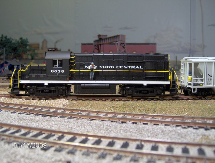
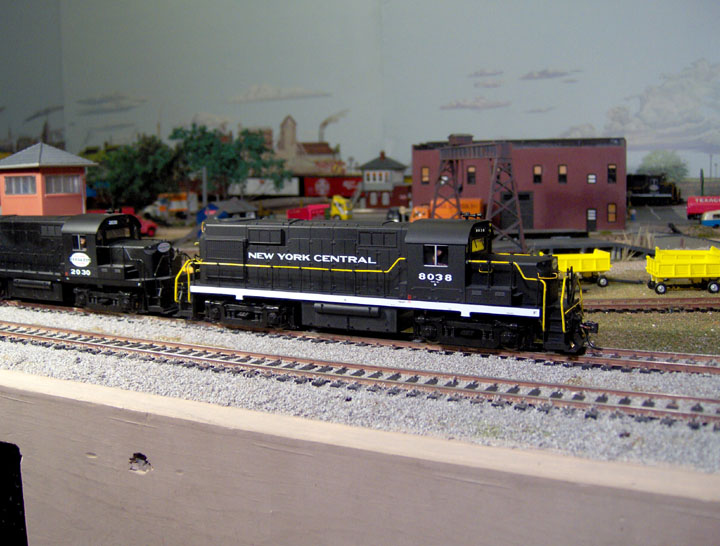
This is NYC RS-32 #8038, an Atlas Trainman RS-32. It is a mechanical twin of its brother NYC RS-32 #2030. I chose this locomotive for the sound installation because most of the detailing on it has been completed. I applied and painted the grab irons, MU and air hoses, and uncoupling levers from a Cal-Scale Super-detail Kit that I purchased from Bowser Manufacturing. I left the lifting rings intended for the panels on top of the hood off for the time being. This photo was originally taken for Weekend Photo Fun Thread on the Model Railroader Magazine's HO Forum. It was also posted on the Sunday Photo Fun thread on the Atlas HO Forum.
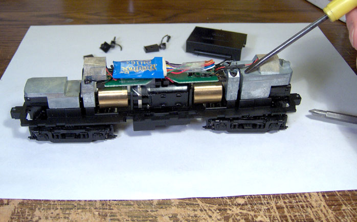
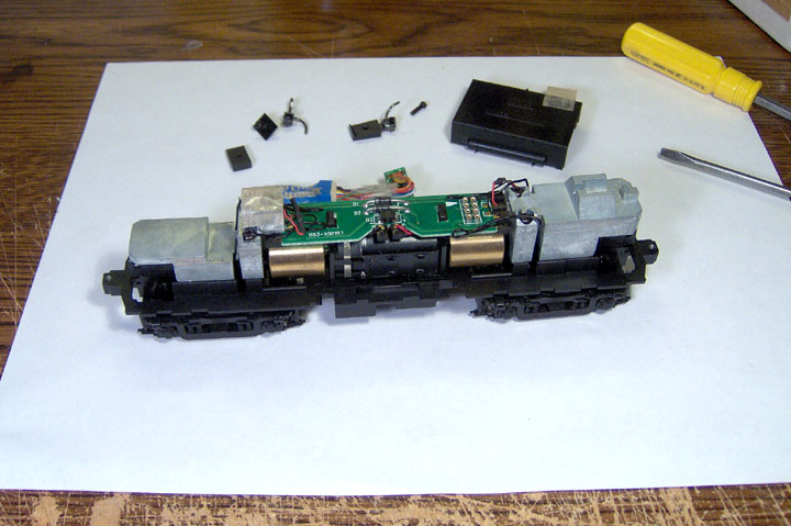
This is RS-32 #8038 with the shell off. Space inside of the shell is at a premium as can be seen in this photo of the intact chassis. Nearly the entire volume of the locomotive's shell is filled, with drive components, circuit boards, DCC decoder or chassis weights. Notice the Digitrax DH163 decoder mounted on top of the circuit board. It was installed so the loco could be operated on the railroad while I waited for the sound decoder to arrive from Litchfield Station.
In most of my other sound loco conversions I had room to mount a speaker horizontally above the rear drive tower or in the cab. Here, to make room for a speaker I considered cutting down the back chassis weight, but because I don't have the tools to do a professional job of modifying the weight and the width of the shell, I would have been limited to a 5/8-inch speaker. The next best option was to remove one of the chassis weights. I decided to remove the rear chassis weight. In the photo the screw driver is pointing to the screw mounted rear chassis weight.
The next step was to remove the Digitrax DH163 decoder, dismount the rear light and get the pick-up wires out of the way of the rear weight. In this photo the decoder, its wiring harness and plug have been removed. The back up light has been moved out of the way and the chassis weight is ready for removal once the pick-up wires are moved aside

Here the rear chassis weight has been removed. A simple task, it was held in place with two Phillips head screws. The weight itself is in the right foreground.
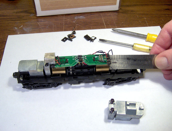
It was time to take some measurements. After looking things over for awhile and taking a few measurements, I determined that I had 1 1/8 to 1 1/4-inches of usable space horizontally from the back of the rear motor flywheel to a point near the rear truck tower/swivel. A one and a quarter inches was crowding things a little so I settled for 1 1/8-inches as the horizontal measurement for my speaker mount.
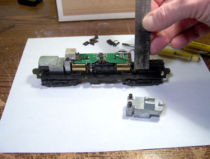
Next I took a couple of vertical measurements. I measured the depth of the loco's shell and then the available height from the top of the chassis weight mount to a point about 1/4-inch above the circuit board. A little exercise in mathematics determined that the height of my speaker mount would have to be 7/8-inch or less. Combining the vertical and horizontal measurements gave me a speaker mount size of 1 1/8-inches x 7/8-inch. One problem remained. How could I mount a speaker or speakers and still clear the rear motor flywheel, drive shaft and tower?
There was the added problem of how to enclose the speaker for good sound quality. It occurred to me that many sound equipped hood unit locomotives have two speakers and enclosures in an "A" frame mount. I also recalled seeing an installation by Bruce Petrarca at Litchfield Station that incorporated the locomotive shell as part of a speaker enclosure. Why not? All I had to do was come up with a design.

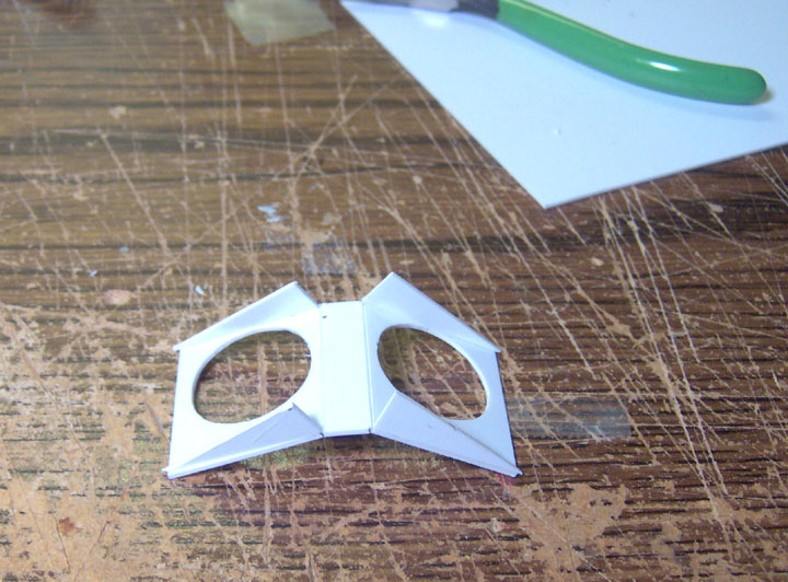
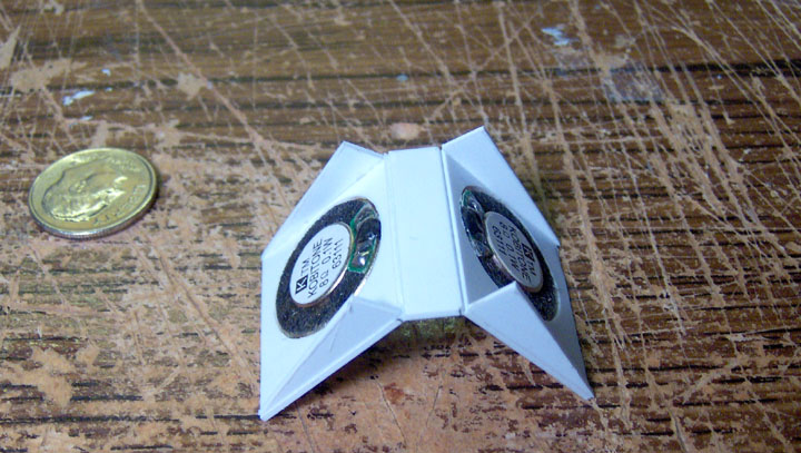
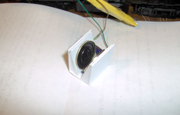
The photo shows the paper template I made of my speaker mounting "A" frame using the measurements I had determined earlier, 1-1/8-in. wide and 7/8-in. high on both sides of a 1-1/8-in. X 1/4-in. hinge piece. I drew two circles 3/4-in. diameter using a dime for a guide on either side of my paper template and then cut the circles out with small scissors. Then I folded it to shape and mounted it to the chassis with a couple of pieces of Scotch tape. I checked for clearances and free movement of the rear truck and was satisfied the idea would work. NOTE: I apologize, but I forgot to take a photo of the paper template mounted on the chassis.
Using a piece of .030-in. thick styrene sheet, I made a duplicate of the paper speaker frame template. I marked the speaker locations with a pencil and a dime for a template. I then cut the holes and fitted the speakers into the mount using my rotary tool and jewelers files. The 1/4-in. hinge was formed by scoring the styrene with a #16 blade and gently bending it to shape. I fastened triangular side pieces, 1/4-in. wide and 7/8-in. long, to the frame with Testors Plastic Cement. These will form the front and back of each of the speaker enclosures. Remember, the locomotive's shell will form the remainder of the speaker enclosures when the chassis is inserted into it. In the photo the frame is complete save for final sanding and a second application of plastic cement.
With repeated test fittings and adjustments with jeweler's files and fine sand paper, I carefully fitted the speakers to the "A" frame. I achieved a near "press-fit" of the speakers into the frame. As added insurance I applied three small drops of hot glue at the joint between the speaker's frame and the "A" frame.
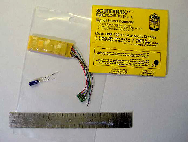
Here is the Soundtraxx DSD-101LC decoder with 3-inch harness, NMRA 8-pin plug and the capacitor that are to be installed in RS-32 #3038. The Soundtraxx decoder is longer, but about the same thickness, as the Digitrax DH163 it is replacing. It will fit comfortably on top of the Atlas' circuit board. Except for the speakers, enclosures and capacitor, this is really a plug and play decoder installation.
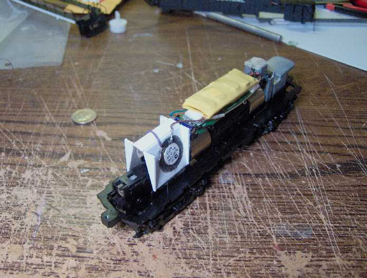
I installed the decoder by inserting the 8-pin plug into the receptacle on the circuit board. Then I folded the 3-inch harness under the decoder and held it in place with a piece of Scotch tape. The decoder is the same width as the circuit board and will slide into the shell without resistance. I installed the rear light inside the top of the speaker frame with a small piece of Krypton tape; as far back as I could get it to line up with the rear light bar. I mounted my speaker "A" frame and speakers on top of the chassis weight mount just to the rear of the flywheel and circuit board with a couple of pieces of Scotch tape.
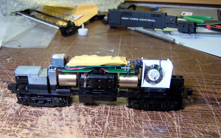
Soundtraxx provides a capacitor for installation with their DSD-101LC decoders. The instructions say "Connect the free GREEN wire to one lead of the enclosed bipolar capacitor...." "Connect the second capacitor lead to one terminal of an 8 ohm speaker." I opted to solder the capacitor directly to one terminal of one of the 3/4-inch, 8 ohm speakers. After drilling a .040-inch hole through the side of the enclosure, and bending the wire into an "L", I inserted and soldered the wire to the left "fireman's side" speaker. I soldered the green wire from the decoder to the other capacitor lead as instructed. Mounted this way the capacitor is rigidly attached to the speaker and isolated from the circuit board and decoder. The photo shows the Soundtraxx decoder nested on the harness wires and held in place with tape. The capacitor is visible just to the left of the top of the speaker frame.
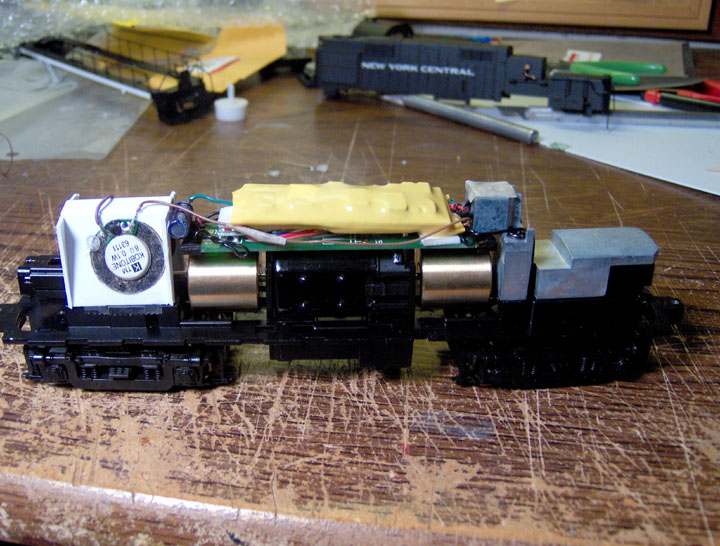
This is the "Engineer's side" of the installation. The second 3/4-inch, 8 ohm speaker is clearly visible as is the capacitor. I soldered the small purple wire at the top left to this speaker and to the free terminal on the other speaker. Then I extended the decoders brown wire and soldered it to the free terminal on this speaker. This connects the speakers to the decoder in series.
With the Soundtraxx DSD-100LC installation complete, it was time to check the clearances around the after truck tower and drive train. With the rear truck at full deflection, there is no contact with the speaker "A" frame. None of the moving parts, i.e., drive shaft, universals or flywheel come in contact with the frame or the speakers. After putting the loco chassis on my programming track to set the address, it was time for a test run.
The locomotive performed well during its test run. All the lights work, and it responded to the functions provided with this limited capability decoder. There are just four functions beyond speed control, bell, lights, whistle/horn and dynamic brake.
The shell slipped on as easily as I had hoped it would. No interference from the decoder or the speaker frame. Once the shell was in place I installed the couplers and placed the loco on the layout for a demonstration run and to test its pulling power with its weight reduced. Happily the loco performs well. It pulled 16 freight cars and a caboose without slippage around my flat BRVRR layout. Since I rarely run a train with more than 12-cars, its capabilities are adequate for my needs. I suspect it will pull 20 or more cars without a problem.
It has been nearly a month since I did this installation and I can still say that I am happy with it. The sound could be a little louder but it is adequate for my small layout and train room. I suspect the small speaker size combined with a restricted enclosure size have some effect on the sound volume. During the test run shown in the photo, I speed matched #8038 with its running mate #2030 using DecoderPro, my home computer and my Digitrax Zephyr. They perform beautifully and the sound enhances the realism greatly.
I hope this short 'photo essay' helps some with your own sound decoder and speaker installations. The steps are essentially the same for most sound decoders, with the exception of the circuit board 'drop-in' decoders. But many of them still require the installation of a speaker or speakers. Good luck!
NOTE: After several weeks of operation I had to open up the locomotive to fix a light bulb. While I was at it I added a piece of styrene to the back of both speaker mounts to fully enclose them. I don't believe the mount to body shell fit was tight enough for good sound projection. The full enclosures enhanced the sound by about 25% I believe. Still not real powerful, but better than it was and I no longer have to run the sound decoder at full output.